
download:
v3 http://www.mediafire.com/?ogke19pbbfs3osv
v2 http://www.mediafire.com/?befx607rhkxr5r1
v1 http://www.mediafire.com/?m50j2fzdbj0bde4
add "active_block_range=5" to your minetest.conf
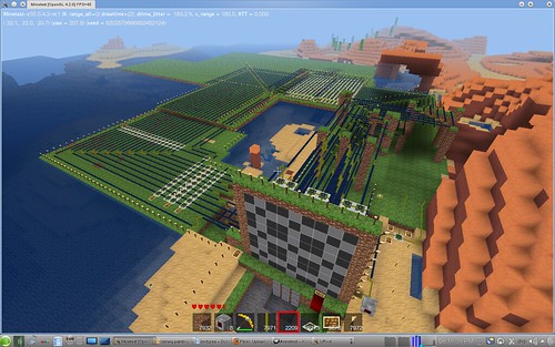
coordinates: (30.7, 2.5, 20.4)
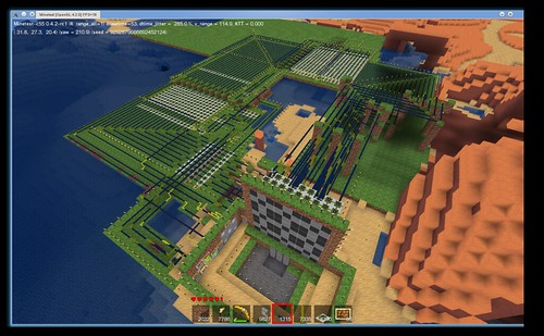
Progressively less outdated pictures:
Problems:
I press some buttons, the board lights up, press reset, the board goes dark, then sometimes the board lights up again. I have wires left on with no source of power/logic for it. There are µcs on each end of the wire, with the relevant ports off.
Pressing the same button twice won't put an X over an O, however, it will change the turn.
The win calculation is working correctly, but it doesn't know when the board is full.
Somehow the blinky plant overheated random chips in the row it was connected to.
Currently:
There is a three-way setting for whose turn it is after a win
a win stops input
You must wait for the whole circuit to load before the board blinks (if you quit during a win) - and I believe for proper operation, too.
Even if you win in two or (three) ways at the same time, it still blinks correctly.
There is a current turn indicator.
There is a setting for blinking the winning line.
It's not quite ready to be entered in the competition yet. Cornernote told me to put this here.

